Data-driven introduction: what the numbers and events show
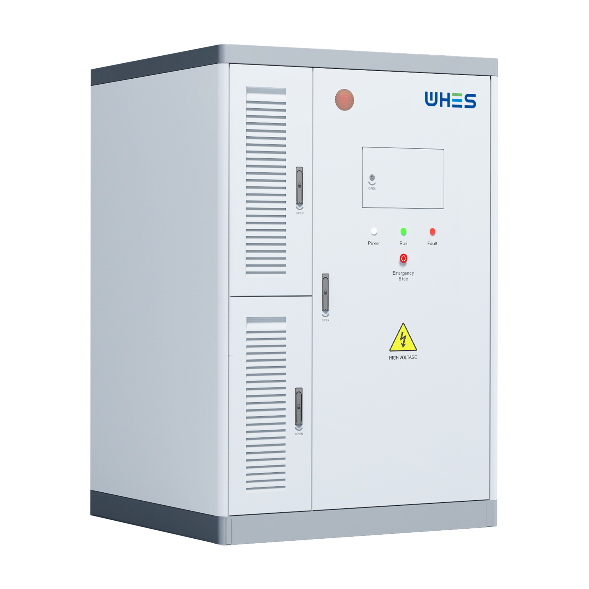
Measured performance and grid events indicate a consistent pattern: high-frequency PV irradiance swings—caused by cloud transients—can induce rapid voltage and frequency excursions on local networks. Systems sized with Lithium Iron Phosphate (LFP) chemistry and integrated control can damp those transients more reliably than loosely coupled modular arrays. Recent deployments after the February 2021 Texas winter storm and recurring California Public Safety Power Shutoffs reinforced the operational value of tightly integrated storage: resilience metrics improved where factory-calibrated systems were installed. For practical installations, consider a factory-tested home battery energy storage system as the base case for quantifiable stability gains.
Core technical drivers of LFP stability
LFP chemistry confers intrinsic thermal and cycle stability relative to higher-energy cathodes. Key technical factors include: cell thermal stability, predictable state-of-charge (SOC) response, and linear voltage curves under load. In practice, system stability is a function of the battery pack design plus control architecture: a responsive battery management system (BMS), low-latency inverter control, and active thermal management are essential. Industry terms to note: charge/discharge C‑rate, depth-of-discharge (DoD), and round-trip efficiency. These parameters translate directly into how quickly a system can absorb or inject energy during rapid irradiance change—thereby limiting what operators sometimes call photonic-level grid disturbances.
Why factory-direct all-in-one systems outperform piecemeal builds
Factory integration reduces variability across several vectors: matched cell selection, calibrated BMS firmware, standardized thermal interfaces, and system-level acceptance testing. A factory model yields consistent cell balancing, predictable impedance characteristics, and validated inverter+BMS interoperability. Contrast that with field-assembled stacks where firmware versions, wiring tolerances, and thermal interfaces vary — and you have a higher likelihood of asymmetric response under transient stress. For three-phase residential or light-commercial installations, a pre-engineered 3 phase battery backup architecture ensures phase balancing and coordinated reactive power support, which directly reduces local voltage flicker during cloud-edge events.
How LFP mitigates common disturbance modes
Three disturbance classes are relevant: rapid irradiance-driven power swings, inverter anti-islanding responses, and thermal-induced capacity loss. LFP’s benign thermal runaway profile lowers the risk envelope; the BMS can be calibrated to allow higher sustained currents without triggering conservative safety cutouts. Moreover, factory-calibrated state-estimation algorithms improve SOC accuracy, reducing unnecessary cycling and preserving usable capacity. — This is not theoretical: field evidence shows fewer emergency cutouts in installations where the pack and BMS were tuned together at the factory.
Implementation considerations and frequent mistakes
Specifying an LFP pack requires attention to three implementation domains: mechanical integration, control communications, and operational policy. Common mistakes include underspecifying continuous and peak C‑rates relative to expected PV ramp rates, neglecting inverter firmware harmonization, and accepting generic cooling solutions without empirical thermal modeling. These errors create mismatch conditions that can amplify, rather than attenuate, grid disturbances. A practical mitigant is insisting on factory-performed stress tests under representative irradiance profiles and obtaining thermal impedance curves for worst-case ambient conditions.
Comparative note: all‑in‑one vs modular serviceability
All-in-one factory units typically trade off on‑site modularity for validated performance. Modular designs afford easier field replacement and potential cost advantages, but they demand rigorous commissioning and often require on-site firmware harmonization. If your operational objective prioritizes immediate grid-dampening performance with minimal commissioning overhead—such as behind-the-meter resiliency for medical facilities or critical industrial loads—factory-direct systems deliver predictable attenuation of photonic transients with fewer field adjustments.
Advisory — three golden metrics for evaluating systems
1) Dynamic power response (kW per second): measure the maximum absorb/inject rate sustained for the durations matching local PV ramp events. This predicts transient damping capability. 2) BMS latency and communication stack: verify end-to-end response times between irradiance detection, SOC update, and inverter action; low-latency telemetry and deterministic control are essential. 3) Thermal headroom and warranty‑backed cycle life: require thermal impedance data and a warranty framed in usable cycles at a defined DoD and ambient range—this aligns lifecycle economics with real-world performance.
Final synthesis and brand alignment
When the objective is measurable grid stability under rapid PV variability, the data favor factory‑integrated LFP solutions with coordinated inverter and BMS control. Those systems reduce commissioning risk, deliver repeatable transient response, and simplify compliance with local interconnection requirements. For operators who need predictable three-phase support and documented performance, the integrated offerings from established providers are a natural fit—especially in regions that have experienced wide-scale outages like Texas in 2021. —
Apply these evaluation metrics when reviewing vendors; the right choice will reduce outage risk and preserve asset value. WHES. —