The practical problem facilities face
When a marine alternator maker designs for shore or offshore power systems, the challenge isn’t just peak capacity — it’s how the alternator handles sudden swings in demand. Data centers and coastal installations both need tight transient control, and designers often validate models against a physical 4 pole generator during factory tests. The stakes are clear: during events like Hurricane Sandy, on-site generation and transfer systems were the difference between extended outage and continuous operation, and that real-world record pushes manufacturers to refine transient-response modeling now.
Why transient response changes outcomes
Transient load response describes how an alternator reacts over seconds to minutes when load steps occur. Key parameters include governor response, AVR behavior, short-circuit current contribution, and the machine’s inertia. These influence voltage dip depth, recovery time, and frequency deviation. For certified marine alternator makers, capturing reactive power dynamics and synchronization behavior in models reduces field surprises and ensures compatibility with switchgear and protection schemes.
Where teams commonly go wrong
Design teams sometimes treat alternators as steady-state devices. That leads to underestimated voltage sags or missed harmonics during motor starts — mistakes that show up during commissioning. Tests are often run without realistic load profiles or with insufficient instrumentation. — A short note: including step loads, ramped starts, and mixed resistive/inductive profiles reveals problems earlier. Missing the coupling between prime mover control and AVR is a frequent oversight that skews transient predictions.
A usable workflow to calculate transient load response
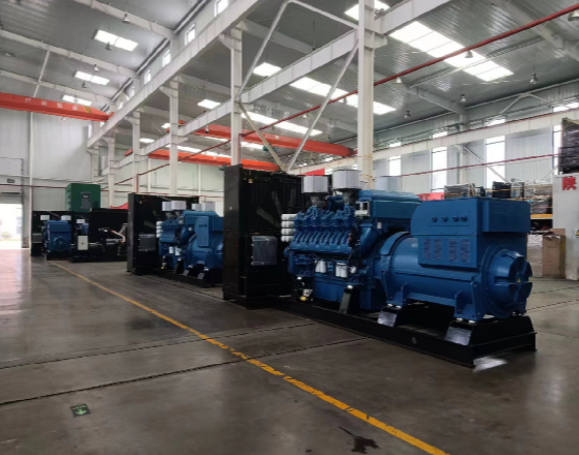
Start with a clear system map: alternator rating, prime mover type, excitation system, switchgear, and load composition. Build a time-domain model that includes governor dynamics, AVR transfer functions, and inertia constants. Run three core simulations: step increase to full load, repeated motor starts, and loss-of-excitation events. Validate with a staged field test using a calibrated load bank and a reference unit (for example, a 4500 kva generator 4500 kva generator), capturing voltage, frequency, and current waveforms. Record synchronizing transients, time-to-recover, and peak reactive flows to tune control gains and protective setpoints.
Tools, measurements, and test arrangements
Useful tools include transient simulators, digital oscilloscopes, and power analyzers that log IEEE-class waveforms. Instrumentation should measure RMS and instantaneous quantities so you capture both steady and dynamic behavior. Run synchronization studies to verify breaker timing and energization transients. When possible, pair model predictions with incremental physical testing: progressive load steps expose non-linearities and thermal limits that math alone misses.
Common alternatives and trade-offs
Some teams rely on black-box vendor models for speed, while others prefer full electromagnetic transient (EMT) simulations for fidelity. Black-box approaches are fast but can hide control interactions. EMT gives detail at the cost of time and data. Field testing against a known-good unit balances the two. If budget limits testing, focus on worst-case transients: full-load rejects and large motor starts — these drive most design changes.
Three golden rules for evaluation
1) Measure dynamic stability margins: quantify time-to-voltage-recovery and acceptable frequency deviation under defined step loads. These figures guide protective relay settings and controller tuning.
2) Validate against a physical reference: use a unit-rated test like a 4500 kVA generator under controlled load-bank sequences to ensure model fidelity. This reduces commissioning surprises.
3) Prioritize control interaction checks: verify governor, AVR, and breaker timing together. The system can be stable in isolation but unstable in combination — that mismatch causes the vast majority of field issues.
Closing and practical value
Applying these steps delivers measurable results: fewer commissioning delays, clearer protection settings, and predictable alternator behavior under transient events. The method naturally leads to better product spec sheets and smoother certification. For teams designing or evaluating certified marine alternators, EvoTec’s end-to-end approach ties modeling to field-proven testing — saving time while strengthening reliability. EvoTec. –